Audvance Audio
Reproduce music the way it was recorded
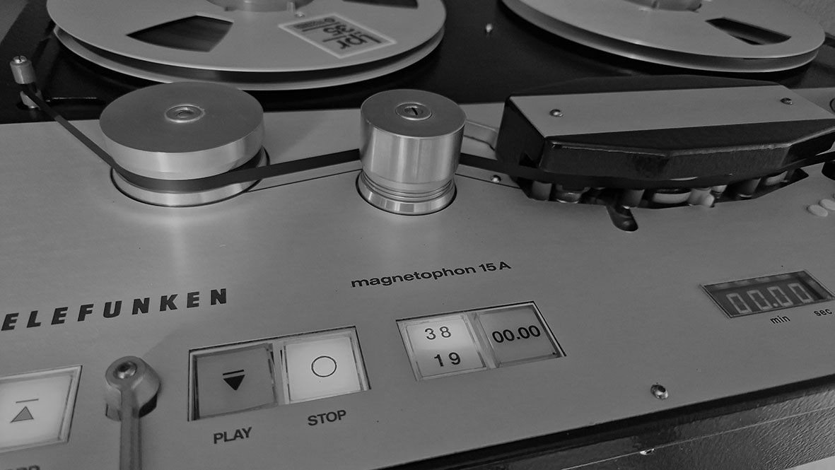
Audvance upgrades for your Telefunken M15A
Audvance has designed new boards for your Telefunken M15A, a recorder with one of the best tape mechanisms in the world ever. In our opinion the audio electronics are lagging behind. With our boards this machine becomes state-of-the-art with true high-end sound quality, challenging any other reference tape machine. Our boards use modern high quality components and completely new designed discrete circuitry on 4-layer circuit boards. Click here to find out what we offer.
Audvance upgrades for your classic Revox B77 or PR99
Audvance has designed new boards for your classic Revox B77 and PR99. These boards use modern high quality components and partly new circuits. The original seventies designs use inferior quality capacitors, resistors and integrated circuits. Although the original Revox boards are well designed and can sound quite good, many improvements can be made. Revox boards had to be swapped to change equalization between IEC and NAB during recording or playback. Basically Revox had three different boards for playback an recording. The Audvance boards offer all three versions on one board and switchable NAB/IEC equalization! You also get higher sound quality, extended bass and a lower noise floor.
Click on the link of your machine below and find out what upgrades are available.

Revox B77/B77MKII 2-track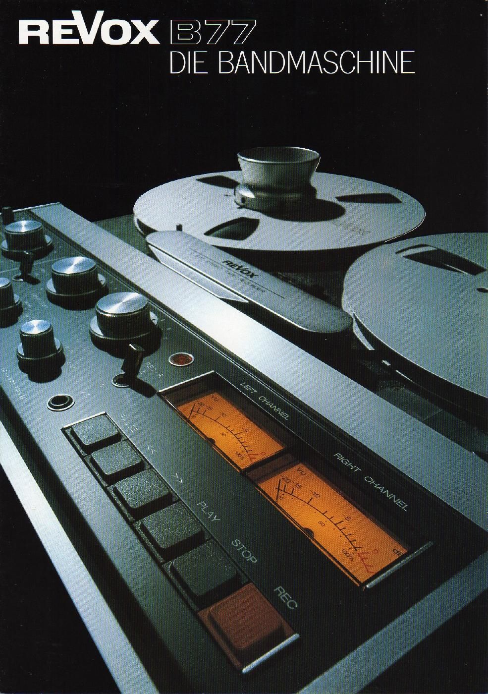 |
Revox B77/B77MKII High Speed |
Revox B77/B77MKII 4-track (no Dolby)  |
Revox B77/B77MKII with Dolby |
Revox PR99 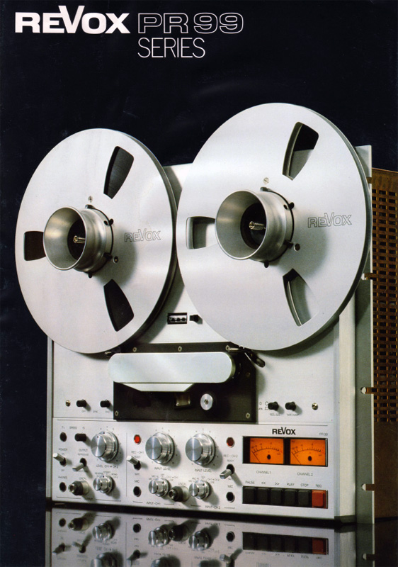 |
Revox PR99MKII 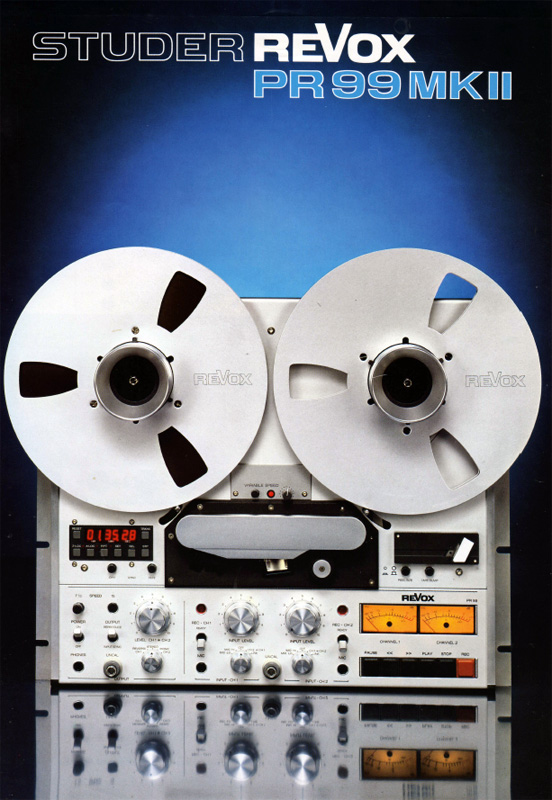 |
Revox PR99MKIII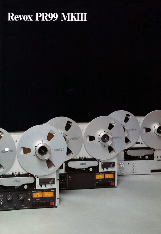 |
All Audvance boards fit most B77/PR99 machines as you can see from the table below. This is why the boards will hold their value very well.

Custom audio design
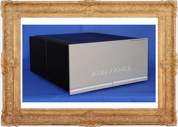
Audvance can realize most of your audiophile dreams with custom design of electronics. This could be electronics for your favorite tape machine, but also amplifiers or what else you would like. Please contact me for more information.
Audvance high-end modules and equipment
⚫ Optical equalizer for DS Audio cartridges EQU-1
The model EQU-1 is an amplifier with equalization for a flat frequency response with all optical phono cartridges from DS Audio. Its power supply has three seperate
power transformers and uses active filtering to create low noise voltages for both the phono cartridge itself and the amplifiers. The short signalpath of the amplifiers contains JFET and MOSFET single ended stages without overall feedback, similar to tube-based designs.
Components are first rate with polypropylene capacitors in the signal path and Vishay/Dale resistors. The sound quality of the EQU-1 is exceptional, just like the DS Audio cartridges themselves. 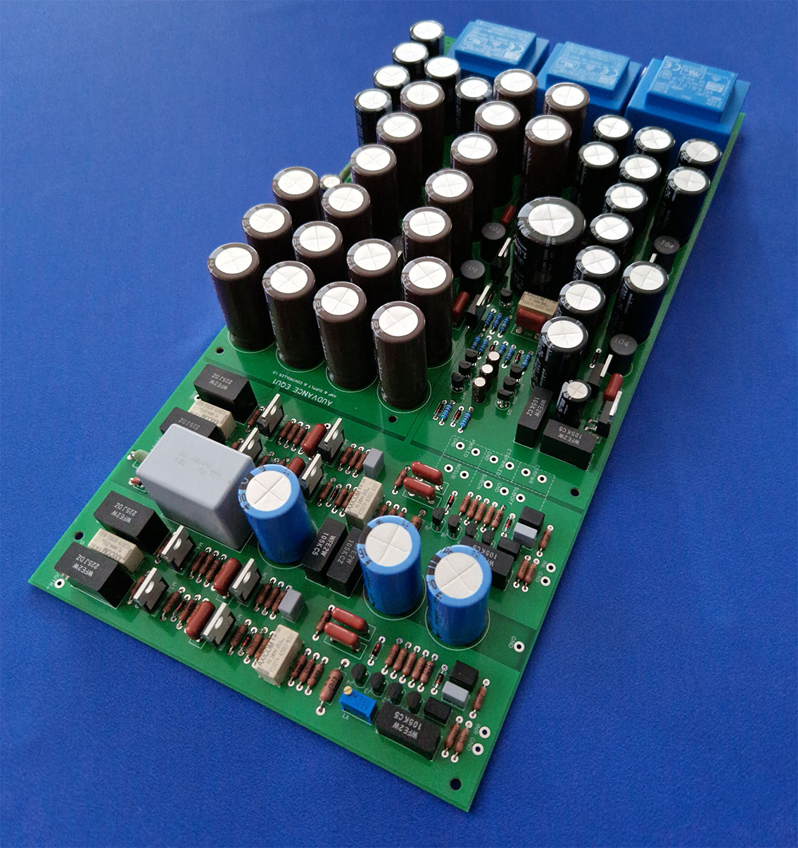
The amplifiers have both single ended and balanced outputs. With most manufacturers the plus or minus output of one balanced output has a slight phase delay since
a signal invertor is used to create a balanced signal from a single ended signal. Not so with Audvance balanced outputs, there is zero phase delay, resulting in higher sound quality. 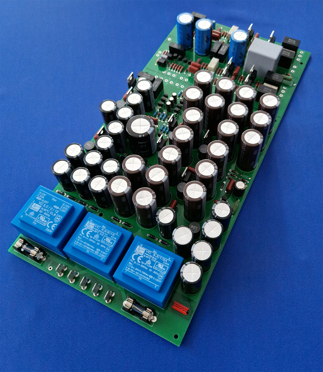
With warped records it is important to have a subsonic filter and
this is implemented (default = on) but can be disabled with a switch. Power can be left on permanently and power to the optical cartridge can we switched on and off with a seperate switch.
The board features an advanced auto-mute system suppressing audible clicks on the outputs with power on, power off and
the cartridge power on or off. Small corrections in the channel balance can be made by means of a trimmer on the board (+/- 0,8dB range). This will be pre-calibrated to 0dB. Instructions for the built can be found here.
Specifications of the EQU-1:
• Mains voltage: AC 240V/50Hz only • Input impedance: 10 KΩ • Minimum output load impedance: 10 KΩ • Output level: 400mV RMS (RCA) or 800MV (XLR) (1kHz) • Harmonic distortion: <0,1 % (1kHz, 70mV RMS input) • Frequency response: 4Hz-300kHz (-3dB) (subsonic filter off) • Subsonic filter: 15Hz (-3dB) (second order) • Dimensions (each module) lxbxh: 325x156x45 mm
There are two choices when you would like to purchase a EQU-1 optical equalizer. Buy the PCB with all parts soldered and put it inside some cabinet yourself, or buy it inside a solid aluminium machined Audvance cabinet, ready to enjoy in your system.
Price for the EQU-1 PCB (without cabinet): € 899
Add to cart
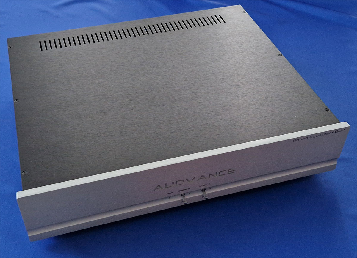
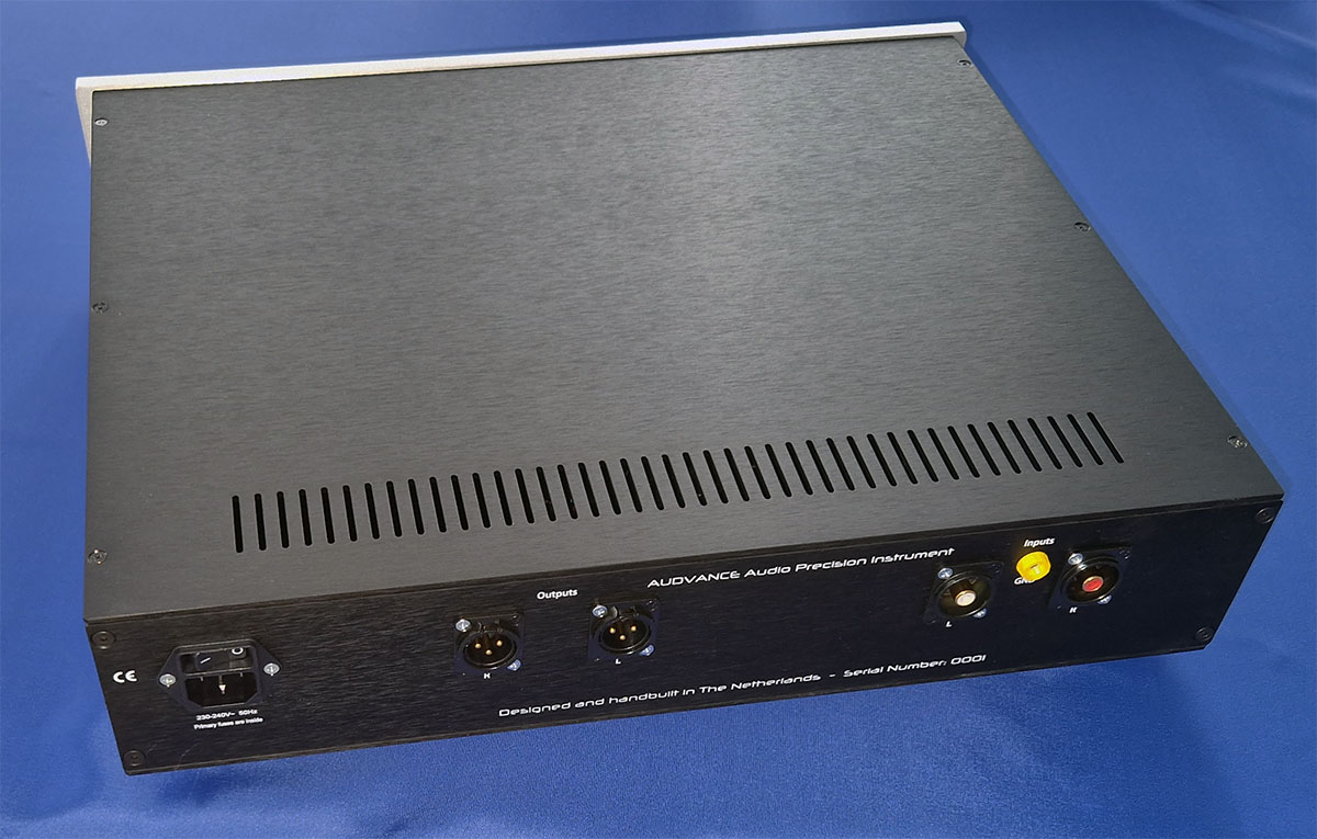
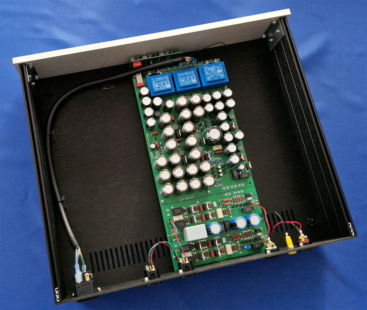
Please find the user manual for the EQU-1 with cabinet here.
Price for Audvance EQU-1 built into machined cabinet with XLR outputs: € 1899
Add to cartPrice for Audvance EQU-1 built into machined cabinet with RCA outputs: € 1899
Add to cart⚫ Balanced headphone power amplifier modules HPA-1
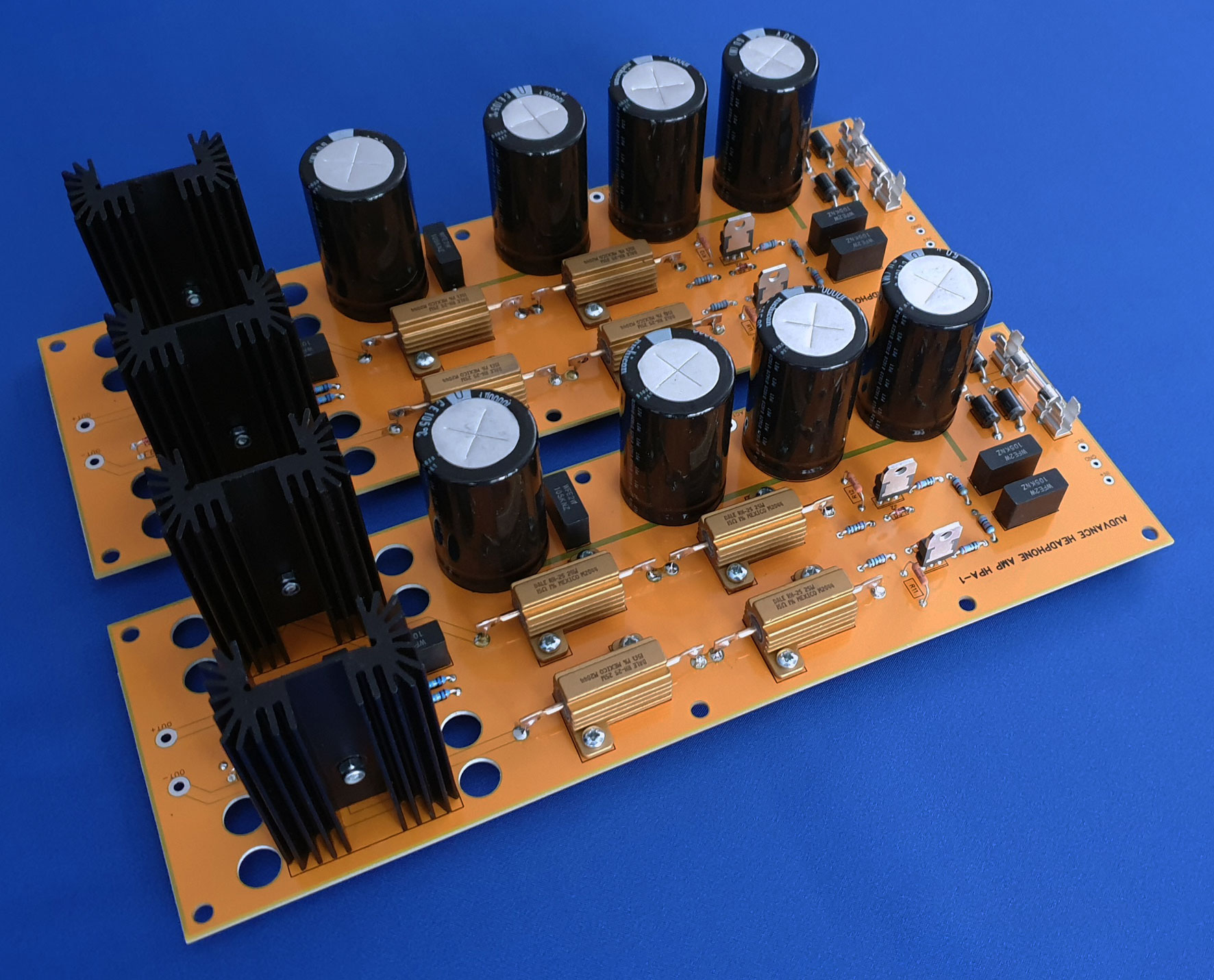
These balanced amplifiers operate with high currents that exceed class-A to improve linearity. The goal is that each transistor faces little variation in its bias. Little variation in bias means little distortion. That is why I prefer to use relative high currents in each stage. Due to the high linearity of the amplifier in itself no overall feedback is needed. Distortion is low enough and even order harmonics dominate, mainly because of the use of MOSFETs throughout. Sound quality is superb, also thanks to the use of just two amplification stages in balanced operation. The first stage realizes the actual amplification and the second stage is a buffer (or current amplifier).
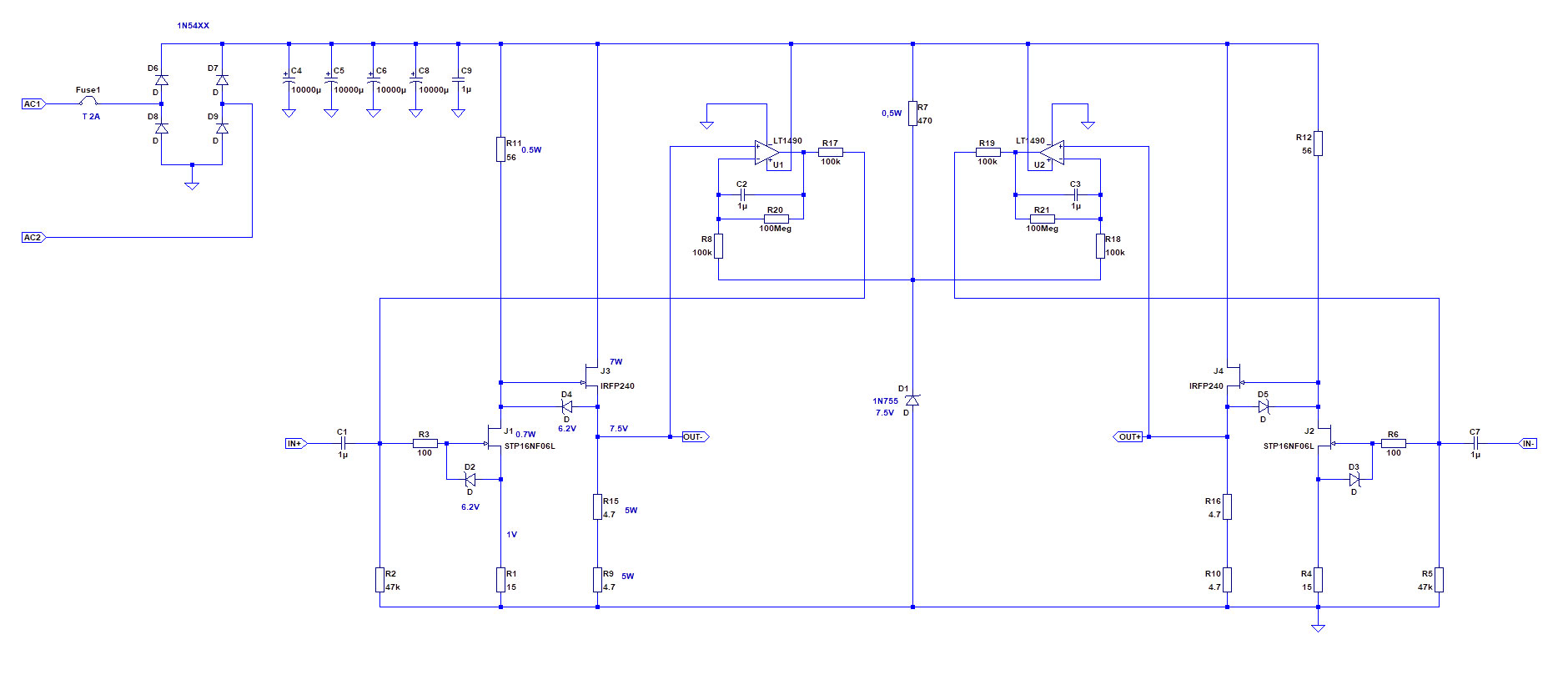
Now let's consider the circuit in detail. MOSFETs J1 and J2 amplify the incoming signal with factor 3,6 each, running at a current of 180mA. This current seems excessive but is needed for a low output impedance (being R11 and R12) to drive the large input capacitance of the second stage. The gates are protected against overvoltage by the zeners D2 and D3. Type STP16NF06L is chosen because of its relatively low input capacitance and resulting in high enough amplifier input impedance at high frequencies. MOSFETs J3 and J4 are very robust ones of the type IRFP240 and carry most of the current (800mA each). They drive the headphone with a low output impedance. These are protected with zeners as well. The output stages on both sides are DC-coupled to the headphone and DC-offset should be low (<5mV) to protect the headphone. This is realized with two DC-servo's that use a common reference voltage, coming from zener D1. The amplifiers U1 and U2 are halves of an LT1490 opamp that is used here as an integrator. It responds to DC only and drives an input current via R17 and R19 in such a way that the outputs OUT- and OUT+ carry both the voltage that is dictated by D1.
Trying to avoid unnecessary feedback there is no regulation in the power supply. Any noise coming from the power supply is common noise with respect to the balanced operation of the amplifier. So there will be no audible hum or noise on your headphone. Balanced operation also reduces the variation in the supply current under load and because of that it reduces variation in the supply voltage itself. That is a major feature of balanced operation.
Keep in mind that the circuit is not protected against short circuits or overheating. Both risks can be avoided however if fixed XLR or jack connectors are used in a well ventilated housing. Instructions for the built can be found here.
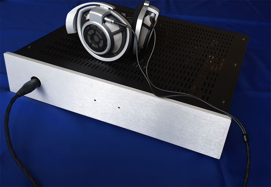
Many high quality headphones operate or can be modified to operate in balanced mode. The headphone cable has to carry four wires all the way to the plug to make this simple modification possible. My own Sennheiser HD800 is modified that way. I cut off the standard plug and soldered on a XLR4 plug. If the cord is detachable like on many you can also simply replace the cord. Many companies offer headphone cables for this purpose.
Specifications of the HPA-1:
• Power output (RMS at 1% THD): 700mW (8 Ω), 1W (16 Ω), 1.7W (32 Ω), 900mW (300 Ω), 450mW (600 Ω) • Input impedance: 15 KΩ (to ground) • Output impedance: <1.5 Ω • Gain: 10dB • Frequency response: 10Hz-600kHz (-3dB) • Power consumption per channel: 32W (25VAC power transformer) • Dimensions (each module) lxbxh: 275x90x66 mm
All things you need to build your stereo headphone power amplifier are:
• One pair of Audvance headphone modules • A mains transformer • Two XLR input connectors • One XLR-4 output connector, or dual XLR3 output connectors • Mains connector with fuse holder • Power switch • Cabling • A cabinet
There are three choices when you would like to own these headamps. Buy the PCB's only, buy a DIY kit with two PCB's and all parts (to mount and solder yourself) or buy completely built modules as shown on the picture (to mount in some enclosure yourself).
Price for a stereo pair of PCB's without components: € 99
Add to cartPrice for a stereo pair of PCB's including all components *): € 299
Add to cartPrice for a stereo pair of PCB's completely built *): € 449
Add to cart*) Components like XLR connectors, cabling, transformers and enclosure are not included in this price.
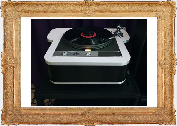
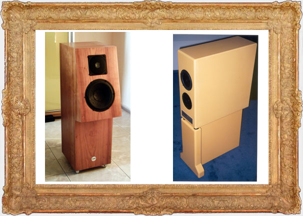
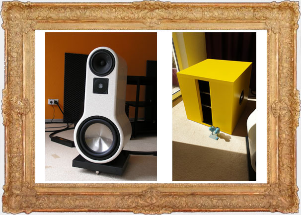
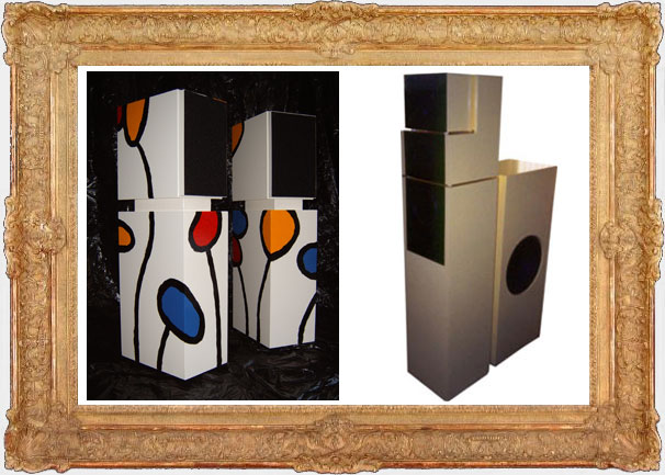
A little history
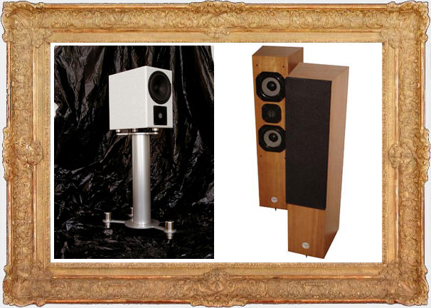
Audio has always been in my blood since I was a 14-year old boy, building my first speakers with some help of my father who was a woodworker. At a very early age I knew that I wanted to study electrical engineering and so I did after I finished high school. I studied at the Technical University in Delft and did my master in analog electronics. Professionally I designed electronics for microchips but audio was my main area of interest. Over the years I designed many speaker systems, both for myself and for others. At a later stage I also designed and built various other items like turntables, amplifiers, tape recorder electronics and many other items. Below you can find pictures of a selection of these various projects ...
